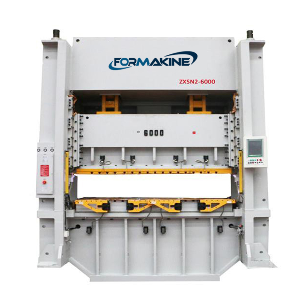
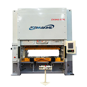
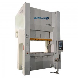
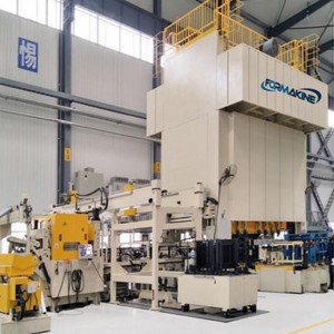
H Frame Double Crank Servo Stamping Press
Standard Configuration
1.Pneumatic die cushion
2.Die pin-hole tap
3.Extended module of electronic rotary cam
(8 spare channel)
4.Automatic slide adjusting device
5.Safety light curtain
6.Power outlet 110V single-phase
7.Power outlet 220V single-phase
8.Anti-Vibration press mounts
9.Tooling light (magnet type, 110V or 220V power source)
10.Air source receptacle
11.Automating peripheral equipment
12.Quick die change system
13.Bottom dead center repeatability detector
14.Electronic hand wheel
15.Safety block with plug
16.Customized forming curves
17.Tonnage indicator
18.Front / back safety door
19.Optical linear scale
Optional Features
1.Operation mode selection
2.Off/Inching/Safety one stroke/Continuous
3.Hydraulic overload protector (H.O.L.P)
4.Automatic slide adjusting device
5.Oil recirculating lubrication
6.Slide & die counterbalancer
7.Programmable Controlling System (PLC)
+10° HMI Operation panel
8.Electronic crank angle display
9.Electronic S.P.M display
10.LCD type Press status monitor
11.Electronic rotary cam switch
12.Misfeed detection socket
13.Digital die height indicator
14.Power outlet
15.Air ejector
16.Air source receptacle
17.Misfeed detection circuit
18.Portable 2-hand pushbutton T-stand
19.Tooling database
Technical Specifications
|
H Frame Double Crank Servo Stamping Press |
|||||||
| Model Parameter |
Double Crank |
||||||
| ZXSN2-2000 | ZXSN2-2500 | ZXSN2-3000 | ZXSN2-4000 | ZXSN2-6000 | ZXSN2-10000 | ||
| Nominal Force | KN | 2000 | 2500 | 3000 | 4000 | 6000 | 10000 |
| Nominal Force Distance | MM | 7 | 7 | 7 | 7 | 10 | 10 |
| Continuous Energy | J | 20000 | 20000 | 27000 | 37000 | 70000 | 110000 |
| Stroke Length | MM | 200 | 200 | 200 | 250 | 280 | 300 |
| Unloaded Continuous Stroke Number | SPM | -120 | -100 | -80 | -90 | -80 | -60 |
| Die Height | MM | 450 | 450 | 550 | 650 | 700 | 700 |
| Slide Adjustment | MM | 70 | 100 | 150 | 100 | 120 | 120 |
| Slide Area (LR*FB) | MM | 1500*800 | 1600*700 | 1800*850 | 2000*900 | 2100*1000 | 2200*1100 |
| Bolster Area (LR*FB) | MM | 1500*1000 | 1600*750 | 1800*1000 | 2000*1000 | 2100*1100 | 2200*1200 |
| Bolster Area Thickness | MM | 200 | 200 | 220 | 250 | 280 | 300 |
| Max. Upper Die Weight | KG | 1500 | 1500 | 2000 | 2500 | 3000 | 4000 |
| Side Opening(FB*H) | MM | 600*400 | 600*400 | 650*700 | 680*600 | 730*650 | 780*650 |

